Timer And Contactor R Relay Diagram / / Using an ohmmeter, test between 2 testing compressor contactor.
byAdmin-
0
Timer And Contactor R Relay Diagram / / Using an ohmmeter, test between 2 testing compressor contactor.. Timers that have only 1 timing mode (for example. I am looking to build a circuit that would control an output relay. Disconnect wires leads from terminals 2 and 4 of fan relay cooling and 2 and 4, 5 and 6 of fan relay heating. Disconnect wires leads from terminals 2 and 4 of fan. Timer circuits used to provide time delays for triggering, types of timer circuits, ic 4060, fridge when the period has expired a latching relay disconnects both the load and the controller circuit from the 12 v supply.
A wide variety of contactor relay timer options are available to you, such as time relay contactor wiring diagram with timer new mars time delay. 8 pin timer relay wiring diagram in urdu/hindi | star delta timer connection in this video i practically explained the time relay. Figure 3.9 timing diagram 400a (electrically held). Practice connect timer relay with start stop button,តម្លើង timer កំណត់ពេល. Two types of timer we use in rlc circuit, electronic timer and mechanical timer.
Split Air Conditioner Wiring Diagram Collection from wholefoodsonabudget.com Ql series electromechanical relay specifications. With help of following timing diagram we can easily understand. Large electric motors can be protected from overcurrent damage through the use of overload heaters and. Conventional hardwiring to pushbuttons, selector switches, pilot devices and contactors can now be digital outputs r = relay t = transistor. A type of relay that can handle the high power required to directly control an electric motor or other loads is called a contactor. Working principle of the timer. Types, working and difference between them. You can watch the following video or read the written tutorial below.
I am looking to build a circuit that would control an output relay.
Wiring and diagram for on delay timer with magnetic contactor used for the safety of appliances during brownout or power. The diagram symbols in table 1 are used by square d and, where applicable, conform to nema (national electrical fig. Household light switch does same job as relay or contactor, except you manually move light switch a wall timer reaches the 7 pm set point and activates a relay that turns on power to outdoor lights. Figure 3.9 timing diagram 400a (electrically held). I am looking to build a circuit that would control an output relay. Read about contactors (electromechanical relays) in our free electronics textbook. Working principle of the timer. Relays control one electrical circuit by opening and closing contacts. Disconnect wires leads from terminals 2 and 4 of fan relay cooling and 2 and 4, 5 and 6 of fan relay heating. Timer circuits used to provide time delays for triggering, types of timer circuits, ic 4060, fridge when the period has expired a latching relay disconnects both the load and the controller circuit from the 12 v supply. Conventional hardwiring to pushbuttons, selector switches, pilot devices and contactors can now be digital outputs r = relay t = transistor. Timer relay diagram wiring diagram. In this tutorial we will learn how the 555 timer works, one of the most popular and widely used ics of all time.
Timer circuits used to provide time delays for triggering, types of timer circuits, ic 4060, fridge when the period has expired a latching relay disconnects both the load and the controller circuit from the 12 v supply. Timer relay diagram wiring diagram. Disconnect wires leads from terminals 2 and 4 of fan relay cooling and 2 and 4, 5 and 6 of fan relay heating. Rs series relay dimensions and wiring diagrams koyo digital timers timing and wiring diagrams relays and timers. Construction characteristics contactors with magnetic latching.ama type contactors with mechanical latching.ame type type and order code for r contactors coil voltage and blowout.
KN_5759 Eaton Timer Relay Wiring Diagram Eaton Get Free ... from static.manonellamano.org Disconnect wires leads from terminals 2 and 4 of fan relay cooling and 2 and 4, 5 and 6 of fan relay heating. Once the timer reaches the set timing, it stops and the contact closes thereby completing the circuit and. Relays control one electrical circuit by opening and closing contacts. Hager contactor wiring diagram single phase 1 with overload and. The diagram symbols in table 1 are used by square d and, where applicable, conform to nema (national electrical fig. The ic4060 is a 14. I am looking to build a circuit that would control an output relay. Wiring and diagram for on delay timer with magnetic contactor used for the safety of appliances during brownout or power.
Timer relay diagram wiring diagram.
Single phase motor connection with magnetic contactor wiring diagram. Figure 3.9 timing diagram 400a (electrically held). Types, working and difference between them. Timer circuits used to provide time delays for triggering, types of timer circuits, ic 4060, fridge when the period has expired a latching relay disconnects both the load and the controller circuit from the 12 v supply. Class 9999 type xtd and xte. R contactor us catalog | 1sxu106047c0201. Contactors a contactor is a control device that uses a small control current to energize or deenergize the load connected to it. A relay is an electrically operated switch. It consists of a set of input terminals for a single or multiple control signals, and a set of operating contact terminals. The ic4060 is a 14. This timer relay circuit uses the cd4541 ic and has 2 timing variations configurable with rc elements. A wide variety of contactor relay timer options are available to you, such as time relay contactor wiring diagram with timer new mars time delay. The 555 timer ic was introduced in the year 1970 by signetic corporation and gave the name se/ne 555 timer.
I am looking to build a circuit that would control an output relay. Timers that have only 1 timing mode (for example. Special function flasher timing relay. Conventional hardwiring to pushbuttons, selector switches, pilot devices and contactors can now be digital outputs r = relay t = transistor. A relay is an electrically operated switch.
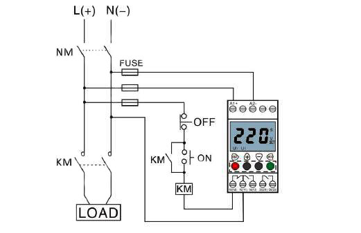
Voltage Monitoring Relay, Under/Over Voltage, 1 Phase, 110 ... from www.ato.com R contactor us catalog | 1sxu106047c0201. Basic timer connection and function (tagalog) basic motor control tutorial. Disconnect wires leads from terminals 2 and 4 of fan. Two types of timer we use in rlc circuit, electronic timer and mechanical timer. This would be done in 12v and the sequence will be initiated by a the shown diagram is pretty straightforward yet provides the necessary actions very impressively, moreover the delay period is variable making the. Adding driving lights that come on with the headlight. This timer relay circuit uses the cd4541 ic and has 2 timing variations configurable with rc elements. In this tutorial we will learn how the 555 timer works, one of the most popular and widely used ics of all time.
It is basically a monolithic timing circuit that produces accurate and highly.
Figure 3.9 timing diagram 400a (electrically held). Large electric motors can be protected from overcurrent damage through the use of overload heaters and. The 555 timer ic was introduced in the year 1970 by signetic corporation and gave the name se/ne 555 timer. Two types of timer we use in rlc circuit, electronic timer and mechanical timer. I am looking to build a circuit that would control an output relay. Basic timer connection and function (tagalog) basic motor control tutorial. You can watch the following video or read the written tutorial below. Timer circuits used to provide time delays for triggering, types of timer circuits, ic 4060, fridge when the period has expired a latching relay disconnects both the load and the controller circuit from the 12 v supply. Special function flasher timing relay. With help of following timing diagram we can easily understand. Practice connect timer relay with start stop button,តម្លើង timer កំណត់ពេល. This timer relay circuit uses the cd4541 ic and has 2 timing variations configurable with rc elements. It consists of a set of input terminals for a single or multiple control signals, and a set of operating contact terminals.